In this post, I'll explain how NodeBox 2 is build as a big graph evaluator and describe how the program arrives at its visual output. I will detail the difficulties in marrying the functional aspects of NodeBox 2 with Processing's imperative nature.
NodeBox 2 as a functional language
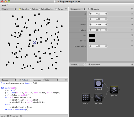
NodeBox 2 is a program where operations are presented as a graph of nodes. Each node fetches data from its inputs, calculates a new result and sends it off to its outputs. In the end, the output of one node gets displayed (this node is marked in the screenshot with a yellow rim).
The underlying data structure is a directed acyclic graph. This is a graph where all nodes have a direction, and where cycles between nodes verboten.
Each node contains a "cook" function. The output of the node (which is stored in its output port) is the return value of this function. We mark one of the nodes as the rendered node. This node is the one we want to cook.
- From the rendered node, find its dependencies. These are the nodes connected to input ports of this node.
- For each dependency:
- Find its dependencies and update them, recursively.
- Cook the node. This executes the cook function and puts the return value in the output port, ready for the dependent nodes to pick it up.
- Cook the rendered node.
- Draw the result of the rendered node.
This approach has a number of benefits:
- There is one clear endpoint, the rendered node. By changing the rendered node, users can look at the output of a node anywhere in the graph.
- The graph is determinate. Cooking the network always gives the same result.
- Unchanged parts of the graph can be cached. We can determine which nodes we need to recalculate whenever something changes by looking at its dependencies. We try to be as lazy as possible. Doing the least amount of work needed is good for speed.
In other words, NodeBox 2 takes some aspects from functional programming, such as "pure" functions and function composition, and makes them visual. Now that I think about it, this explains my fascination for Clojure.
Processing is a state machine
We'd like to integrate Processing into the network. Processing provides an API for drawing, interactivity and animation.
The design of Processing is quite different. Processing is designed as a state machine. This has a number of effects:
Here is a simple Processing example that demonstrates its stateful nature.
  void draw() {
    if (mousePressed) {
      fill(255);
    } else {
      fill(0);
    }
    ellipse(mouseX, mouseY, 50, 50);
  }
And here's what it looks like:
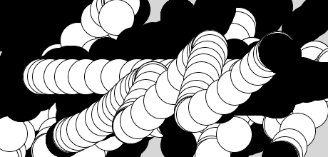
Note that we don't specify the fill color in the ellipse. Instead, we set the fill color. All commands that draw something, from that point on, will use this new fill color. Also note that the ellipse command immediately draws something on the screen.
In other words, all Processing commands have side effects. We don't care about their return value, but we call them because they change something in the world. Processing is an imperative language.
Compare this to the typical code of a node:
  def cook(self):
    p = Path()
    p.rect(self.x, self.y, self.width, self.height)
    p.fill = self.fill
    return p
This code doesn't draw anything! All it does is create a Path object with the right geometry and color and return it. It is free of side effects. You could call this code many times, or not at all if you already have the cached result.
The basic problem is as follows:
- We can no longer be sure that a node has no side effects. Quite the contrary! Processing is all about managing state.
- There is no clear endpoint or "rendered node". Instead, the render is a result of calling the commands.
- The order in which nodes are cooked is important.
- Caching doesn't work since the functions have to be called for them to have an effect.
- There is no data involved! In the Processing example, nothing gets passed on.
Processing → Graph
Let's try converting our simple Processing example into a node network.
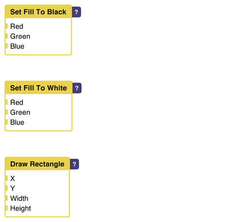
We'll start simple by drawing a rectangle.
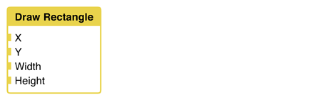
This node has a number of connection points, or ports that can be connected. As in the example, we'll connect the X and Y coordinates to the mouse.
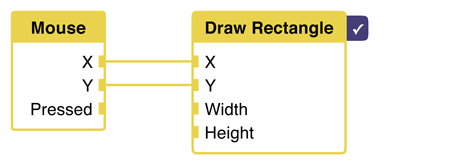
Now, the rendered node comes into play. Since we have more than one node, we need to know which one to render. Here, we want to see the result of drawing the rectangle. The mouse node is a dependency.
We haven't set a color though. Let's do that now.
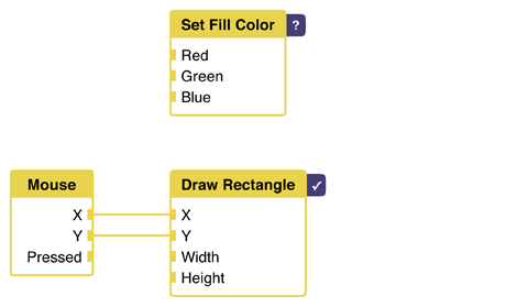
Uh-oh. We've run into a problem. As said before, we now have two rendered nodes. One that sets the fill color, and one that draws the rectangle. In which order do we execute them? How do we specify this order?
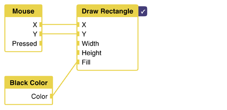
Let's work around the problem. We'll give the draw rectangle node a "fill" attribute. Then, inside of the node, we call the Processing "fill" command first, and than the "rect" command.
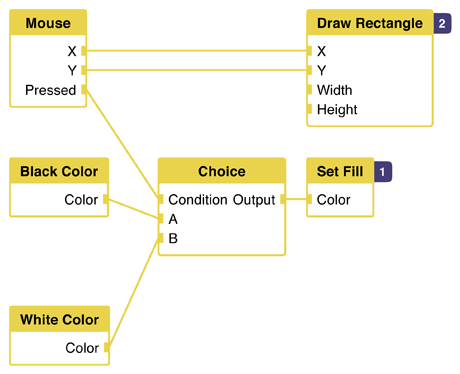
We know set only one fill color. Remember, from our code, that the fill color changes depending on if the mouse was pressed or not. This means we'll need two colors, and some way to choose between the two.
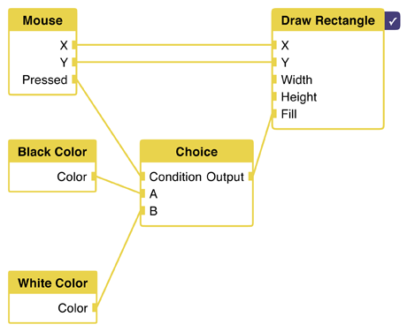
The choice node does the trick. It checks a boolean value, "condition", which is connected to the mouse pressed port. If the condition is true, its output is set to input A. Otherwise, if the condition is false, we'll set the output to input B.
By having the choice determine the color, we can now use this color as the fill for our rectangle node.
This whole "fill" port feels like cheating though. What if there is more state we need to set? Will we need a huge list for each node that draws something? Imagine that the state itself is order-dependent: setting a rotation before a translation has a different effect than the other way around. In which order do we set the state inside of the node itself?
Clearly, if we want to fully support the stateful nature of Processing, we need a different solution.
Quartz Composer does this by tagging each node with an order number. Instead of one rendered node, we now have a list of nodes that needs to be executed in the specified order. Without the "mouse pressed" condition, the graph can look as follows:
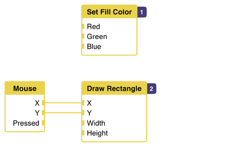
By specifying the order, we make state ordering explicit. In this graph, the fill node is executed first, setting the global state fill color. After that, the "draw rectangle" node is evaluated, which processes its dependencies (the mouse) first after drawing something itself.
This seems like a good solution! By tagging the nodes with an order, we can choose the ordering.
How does this look when we add a condition? I don't know:
We can't execute both the black and white nodes, because they would set state and the last one would win. Also, we can't use a condition node since none of them have an output. They just set state.
One solution is to pass data around until the very end. In this example, we would choose between two color objects (that don't set state), then finally set state after we've chosen.
This works for this case. However, it is not sustainable for every kind of state.
The semantics of the network need to change to adapt this imperative way of handling code. In a way, it becomes a wrapper around the constructs we use in programming: conditions, loops, functions, etc. Figuring out these semantics will be part of my research project.